
13

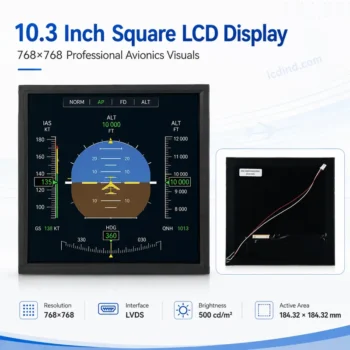
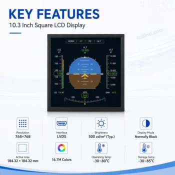
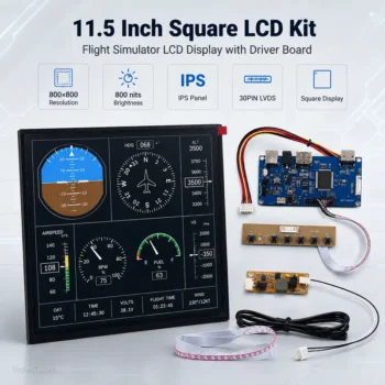
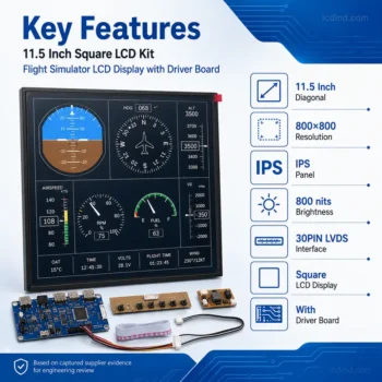
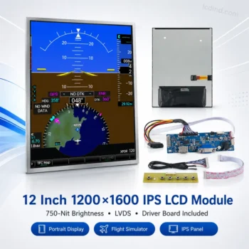
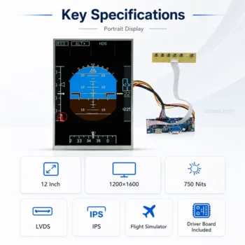
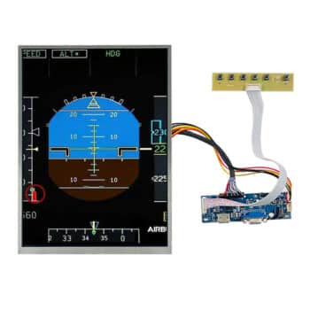
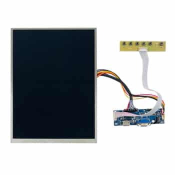
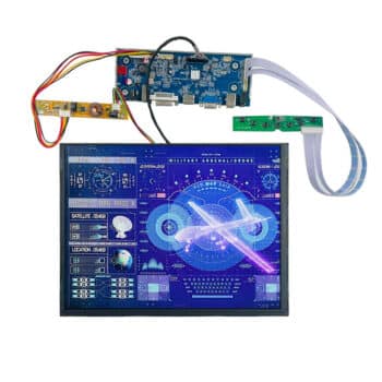
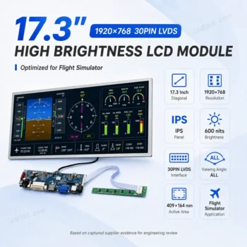
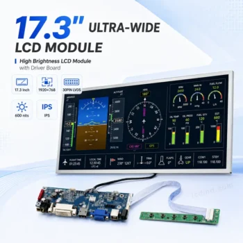
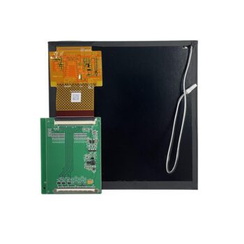
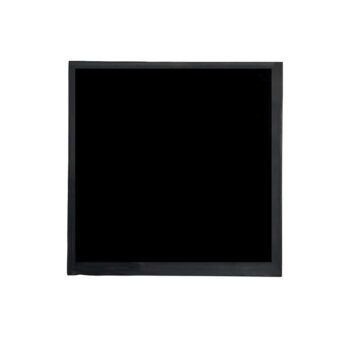
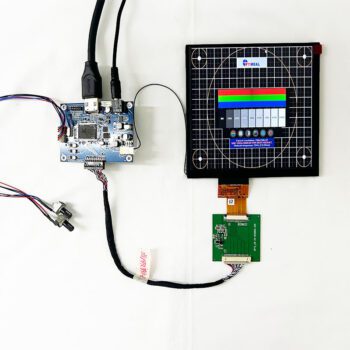
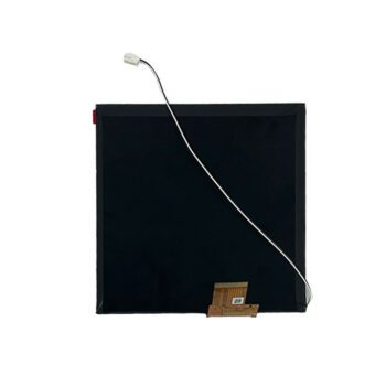
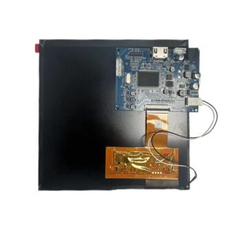
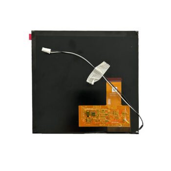
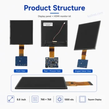
Mechanical fit
- Panel opening, active area and outline
- Bezel overlap and visible pixel margins
- Thickness, mounting points and connector position
- Portrait, landscape or round-mask orientation
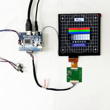
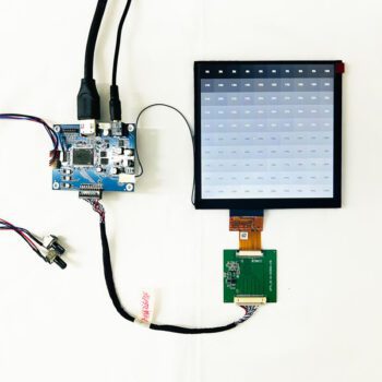
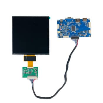
Universal LCD Controller Board solutions. Convert HDMI/VGA signals to LVDS, EDP, or MIPI. Custom firmware support for industrial display panels.
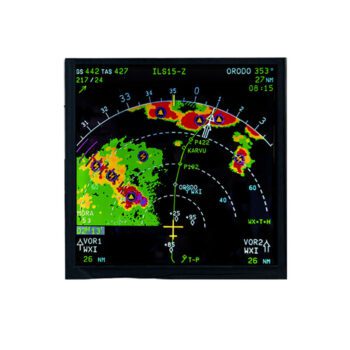
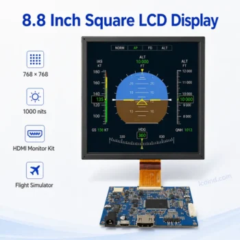
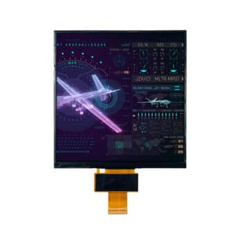
Specialized Flight Simulator Displays for aviation training and cockpit simulation. Custom aspect ratios and bezels designed to replicate Boeing, Airbus, and Garmin avionics instruments.
Showing all 15 results
Cockpit and navigation displays must match the instrument opening, native resolution, viewing distance and host output. Select the LCD, controller, touch or bezel stack as one system instead of choosing by diagonal size alone.
| Display position | Typical requirements | Inputs to confirm |
|---|---|---|
| G1000 / glass cockpit | High pixel density, square or portrait format, readable text and stable scaling | Visible window, native resolution, HDMI/DP host output, bezel and backlight control |
| MCDU / CDU | Compact active area, correct aspect ratio, optional touch and shallow depth | Cutout drawing, resolution, interface, key/bezel integration and cable exit |
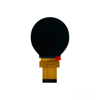
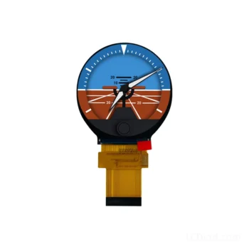
| Round gauge | Circular visible area, square or round pixel matrix and controlled black level | Visible diameter, mask geometry, native pixels, viewing angle and controller |
| Marine / navigation panel | Brightness, dimming, viewing angle and enclosure compatibility | Ambient light, night mode, optical stack, temperature and mounting |
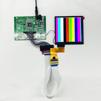
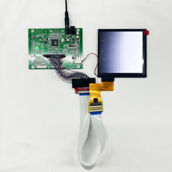
A raw LCD module offers the smallest mechanical package but requires correct panel timing, power and backlight control. A controller kit adds HDMI or DisplayPort conversion and may simplify simulator integration. An enclosed or open-frame monitor adds mounting and power functions but requires more depth. Choose the integration level before requesting a model match.
For replacement projects, send the existing LCD model, datasheet, controller board, cable drawing and instrument cutout. For a new design, provide the visible area, native resolution, host output, brightness/dimming requirements, touch need, prototype quantity and annual quantity.
Related resources: square LCD modules, round TFT displays, and LCD controller board solutions.
Usually not. Most raw modules need an HDMI or DisplayPort controller that supplies the correct LVDS/eDP/MIPI timing, voltage and backlight control.
Yes whenever possible. Native output avoids scaling artifacts and makes instrument text and lines sharper.
Yes if the active area covers the visible diameter and the bezel masks unused pixels. Confirm the safe content area and black level.
The controller and backlight driver must support the required PWM or analog dimming range. Confirm minimum brightness and color behavior in the assembled system.
Provide the existing panel model, datasheet, cutout, controller, cable, host output, brightness, sample quantity and annual quantity.
Send the instrument cutout, target resolution, host output, brightness/dimming requirements and quantity. We will assess the LCD, controller and mechanical fit before quotation.
🔒 Your data is secure. We usually reply within 24 hours.