13
2.8 Inch TFT LCD Module for Resistive Touch HMI
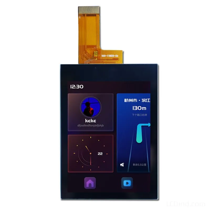
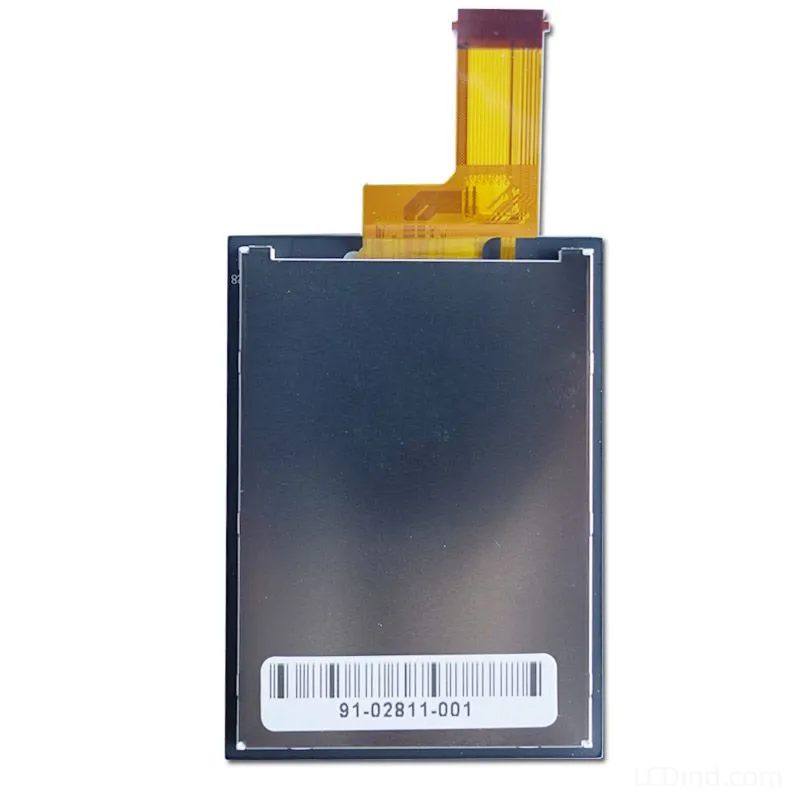
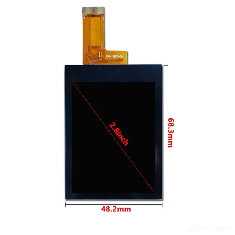
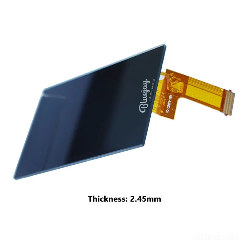
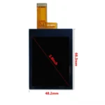
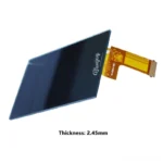
2.8-inch 240×320 MCU TFT LCD for compact resistive-touch HMI projects, with 600-nit brightness, 3.3V supply, -20 to +70 C operation, and a 48.2 x 68.3 x 2.45 mm module outline.
Product Attributes
| Brand | OEM / ODM |
|---|---|
| Size | 2.8 inch |
| Resolution | 240×320 |
| Interface | MCU |
| Brightness | High Brightness (500-900 nits) |
| Operating Temp | Industrial (-20 ℃ to +70 ℃) |
| Touchscreen | Resistive Touch (RTP) |
Description
2.8-Inch 600-Nit MCU TFT with Resistive Touch for Compact HMI
This 2.8-inch TFT LCD module combines a 240×320 portrait display, MCU interface, 600-nit backlight, and a resistive touch panel in the confirmed configuration. It is designed for compact operator interfaces where a gloved finger or stylus may be used to enter settings, acknowledge alarms, or move through a small number of control screens. The 43.2 x 57.6 mm active area is contained within a 48.2 x 68.3 x 2.45 mm module outline.
The module is not simply the touch version of every other 2.8-inch display. Its outline, thickness, touch layer, optical behavior, FPC arrangement, input electronics, and firmware workflow must be evaluated as a complete assembly. It is most appropriate for OEM teams that can integrate the MCU display path and resistive-touch input into their own embedded controller.
Locked Technical Parameters
| Display size | 2.8 inch |
|---|---|
| Resolution | 240×320 |
| Display interface | MCU |
| Brightness | 600 nits |
| Touchscreen | Resistive touch panel |
| Operating temperature | -20 to +70 C |
| Outline dimension | 48.2 x 68.3 x 2.45 mm |
| Active area | 43.2 x 57.6 mm |
| Power supply | 3.3V |
| LED lifetime | 20000 |
These are the confirmed selection values. Final production approval requires the current drawing, display-interface details, resistive-touch connection information, samples, and testing in the customer’s completed HMI. No controller IC, touch-controller circuit, or certification should be inferred where it is not explicitly documented.
When Resistive Touch Is the Practical Input Method
A resistive touch panel responds to pressure, making it useful for interfaces operated with many work gloves, a passive stylus, or a firm fingertip. This can suit service equipment, machine setup panels, test instruments, and compact controllers where the operator selects defined buttons rather than using consumer-style multi-touch gestures. The input can remain understandable even when the system has only a few commands and screen space is limited.
Resistive technology has different design priorities from projected capacitive touch. The UI should use adequately sized buttons, visible pressed states, and deliberate confirmation for critical commands. Fine targets may be practical with a stylus, but they are not automatically practical for a gloved operator standing beside equipment. The customer should define the smallest glove type, expected touch force, stylus material, operating angle, and whether the panel may be wet or contaminated.
Calibration and coordinate handling belong in the system design. Firmware should define how calibration data is stored, how drift or replacement is handled, and what occurs if a touch remains active during startup. The team should test edge targets, corners, repeated presses, long presses, and rapid operation on the real assembly. A visually aligned button is not sufficient if mechanical tolerance or calibration causes the sensed position to move outside it.
Building a Safe 240×320 HMI
At 240×320, the interface should prioritize the task rather than imitate a large desktop panel. A practical screen can show the machine state, one primary value or setting, a compact alarm area, and a limited set of actions. Deep navigation and dense tables increase both touch errors and operator training time.
Use a clear separation between navigation, value adjustment, and machine commands. A start, stop, reset, or parameter-write function should not sit beside a routine page-navigation target without visual and procedural distinction. Where the equipment risk assessment requires a physical emergency stop or safety-rated control, the touchscreen must not be presented as a substitute.
For numeric entry, step controls or a compact keypad can be more predictable than dragging small sliders. Show units and allowed limits beside the value. After a change, display whether it has been applied, is pending confirmation, or was rejected by the controller. Alarm acknowledgement should not hide the underlying cause or imply that the machine condition has been corrected.
Localization must be tested early. A button sized for a short English word may not hold a translated instruction. The team should check the longest language, numeric range, decimal precision, warning text, and maintenance messages before defining the bezel or fixed touch map.
Optical Stack and the 600-Nit Backlight
The confirmed 600-nit brightness provides useful margin for an HMI placed behind a resistive touch layer and protective front surface. Touch layers, adhesives, air gaps, overlays, and surface reflections can reduce the brightness and contrast perceived by the operator. The complete stack should be tested in the intended ambient light.
This brightness level should not be converted into an unsupported guarantee of direct-sunlight readability. If the machine will operate outdoors or beside strong directional lighting, specify the measured or expected illuminance, viewing distance, viewing angle, window construction, duty cycle, and internal thermal conditions. LCDind can then review whether the standard configuration, surface treatment, optical bonding approach, or another display is appropriate.
A brighter backlight also affects power and heat. In a sealed control housing, internal temperature can rise above ambient because of the processor, power supply, motor drive, or sunlight on the enclosure. Validate the display at its actual location and consider automatic or operator-controlled dimming if the HMI is also used in low light.
Mechanical Integration of Display and Touch
The full 48.2 x 68.3 x 2.45 mm outline governs the mounting envelope; the 43.2 x 57.6 mm active area governs the image window. The touch-sensitive and viewable areas must be coordinated with the front-panel opening and printed border. A tight mask can hide pixels or obstruct useful edge-touch positions after tolerance stack-up.
Review the enclosure section, gasket, adhesive, connector clearance, FPC bend radius, PCB location, and any raised bezel. The front construction should protect the touch surface without causing persistent pressure that produces false input or deforms the assembly. If the HMI requires ingress protection, the sealing concept must be validated as part of the finished equipment rather than inferred from the module.
Operator cleaning is another mechanical and materials question. Define the approved cleaning method, chemicals, frequency, and abrasion exposure. If a replaceable protective film or custom overlay is planned, include it during touch-force, visibility, and durability tests. The equipment manufacturer remains responsible for confirming material compatibility.
MCU Display Path and Touch Electronics
The MCU display interface and the resistive-touch signal path are separate integration topics. For the display, confirm bus definition, pinout, timing, voltage, initialization, update rate, reset behavior, and graphics-memory requirements. For touch, confirm the electrode connection, measurement circuit or controller, coordinate conversion, filtering, debounce, calibration, and fault behavior.
Noise can appear when the display, backlight, switching power supply, motor loads, or long cable routes operate together. Prototype evaluation should check touch stability while the backlight is dimmed, communications are active, actuators switch, and the equipment is connected to its normal power source. Grounding, cable routing, filtering, shielding, firmware averaging, and enclosure construction may all influence the result.
The 3.3V value is part of the confirmed display specification, but it does not define the complete HMI power budget or every touch-circuit requirement. Review the current documentation and proposed schematic before laying out the production board.
Suitable Project Patterns and Important Limits
This module can be evaluated for compact machine setup terminals, calibration instruments, laboratory equipment, portable maintenance controllers, sensor configuration panels, dosing or pumping interfaces, small diagnostic tools, and other embedded HMIs that use a limited number of well-defined touch actions. Application examples do not represent regulatory approval or guaranteed compatibility.
It is not an automatic fit for gesture-based interfaces, high-detail graphics, wide dashboards, standard HDMI systems, or projects requiring capacitive multi-touch. A stylus-oriented interface can use smaller targets than a glove-operated interface, so the intended operator method must be stated. Likewise, a 2.8-inch screen may be too small if several values must be compared simultaneously or if instructions must be read at a long distance.
The -20 to +70 C operating range is a module parameter. The complete equipment still needs validation for internal heat, cold start, condensation, vibration, shock, ESD, EMC, ingress, chemicals, UV exposure, and any sector-specific standards. LCDind can support display selection and drawing review, but qualification of the finished HMI remains the equipment manufacturer’s responsibility.
Prototype Test Plan
- Confirm display initialization, color, orientation, refresh behavior, reset recovery, and power cycling.
- Check touch calibration at the center, edges, and corners using the actual glove or stylus.
- Measure whether repeated presses, long presses, and rapid menu operation are interpreted correctly.
- Evaluate visibility behind the production-intent overlay under minimum and maximum ambient light.
- Test touch stability during backlight dimming, communications, switching loads, and normal equipment operation.
- Inspect the complete tolerance stack, FPC route, connector retention, gasket load, and enclosure depth.
- Run representative hot and cold operating sequences inside the assembled device.
- Record the approved drawing, firmware, calibration process, inspection criteria, and exact sample configuration.
Procurement and Customization Review
Before requesting a production quotation, provide the HMI function, enclosure and PCB drawings, display and touch connection proposal, required brightness, operator method, environmental conditions, prototype quantity, annual forecast, and program schedule. If this is a replacement project, include the existing panel model and original drawing rather than relying on the shared 2.8-inch size and 240×320 resolution.
Possible customization topics may include FPC length or direction, connector orientation, brightness, touch construction, printed overlay or cover lens, bonding, packaging, and batch-inspection requirements. Availability, tooling, MOQ, schedule, and performance must be confirmed for the specific project; none of these options should be treated as included in the standard configuration without written confirmation.
Engineering FAQ
Does resistive touch work with gloves?
Pressure operation can support many gloves, but performance depends on glove stiffness, finger shape, target size, required force, overlay, and enclosure. Test the actual glove and user workflow on a production-intent sample.
Is a separate touch controller required?
The system needs a method to measure and interpret the resistive-touch signals. Confirm the documented touch connection and decide whether the host circuit or a suitable controller will perform measurement, filtering, and coordinate conversion.
Can this screen replace a capacitive-touch module?
Not as a direct assumption. Resistive and capacitive systems differ in mechanics, optics, electronics, gestures, cover construction, and firmware. Select the technology according to operator and environmental requirements.
Is 600 nits sunlight readable?
Brightness alone does not establish sunlight readability. Reflections, touch transmission, cover surface, contrast, UI colors, viewing angle, temperature, and ambient illuminance must be evaluated in the complete assembly.
Can safety-critical machine controls be placed on this HMI?
The equipment manufacturer must complete the applicable risk assessment and standards review. A general-purpose touch interface should not replace a required safety-rated emergency stop or other mandated physical control.
What should be frozen before volume production?
Freeze the approved module drawing, interface and touch documentation, sample configuration, calibration method, firmware, front-panel stack, inspection criteria, packaging, and change-control expectations.
For engineering review, send the front-panel drawing, host-board information, resistive-touch input plan, operating environment, quantities, and qualification schedule through the LCDind RFQ channel. The response can then address the actual HMI assembly rather than only the diagonal size.
Additional information
| Brand | OEM / ODM |
|---|---|
| Size | 2.8 inch |
| Resolution | 240×320 |
| Interface | MCU |
| Brightness | High Brightness (500-900 nits) |
| Operating Temp | Industrial (-20 ℃ to +70 ℃) |
| Touchscreen | Resistive Touch (RTP) |
About brand
Source OEM / ODM LCD panels for OEM, replacement and industrial integration projects. Submit size, resolution, interface, brightness, lifecycle and annual quantity for review.
Engineering FAQ
Q: Can this 2.8 inch TFT LCD module be supplied with a touch screen?
A: The standard listing is Resistive touch panel. LCDind can review resistive touch, capacitive touch, cover lens, bonding, and controller matching when the finished device needs operator input.
Q: What customization options are available for this display?
A: Common custom work includes brightness tuning, FPC length, connector direction, cover glass, logo placement, touch integration, bonding, packaging, and production inspection requirements.
Q: How should the MCU interface be confirmed?
A: Confirm timing, pinout, voltage, cable direction, firmware support, and EMC layout with the host board before sample approval. LCDind can review drawings and interface notes before production.
Q: Can the brightness be adjusted for a different environment?
A: The confirmed brightness is 600 nits. If the display is used behind cover glass or in stronger ambient light, share the target environment so LCDind can review backlight and thermal options.
Q: What information should buyers send for an RFQ?
A: Send quantity, forecast, interface, mechanical drawing, brightness target, touch requirement, operating temperature, logo needs, and any current panel model or datasheet.
Q: Is this display suitable for outdoor equipment?
A: This module is mainly for compact equipment and controlled-light use. For outdoor or direct-sunlight projects, LCDind should review brightness, cover glass, bonding, thermal design, and sealing requirements first.
Shipping and Delivery
Q: What is the MOQ?
A: The MOQ for our products is 1 piece. We are able to provide support throughout the testing process.
Q: What about the delivery time?
A: We have products in stock and can ship them within 3 working days.
Q: Does your product have any warranty?
A: Yes, we offer a warranty that ensures the LCD will function properly upon receipt. However, please note that we do not provide guarantees for any damage caused during use.
Q: What’s your payment method?
A: We accept several payment methods, including T/T (bank transfer), and PayPal.
Q: What’s your shipping method?
A: Thank you for your inquiry. We offer various shipping methods to suit different needs.
For small quantity orders, we use UPS Air-Express, DHL, FedEx, TNT, or EMS Express service. These options are safe and fast.
For large quantity orders, we typically work with the buyer’s cargo agent in China. Alternatively, we can arrange for air or sea transportation.
Please let us know your preferred shipping method and we will do our best to accommodate your request.
Q: Do you offer custom solution?
A: Yes, we offer custom solutions if our standard products do not meet the buyer’s requirements. Please let us know your specific needs, and we will work with you to create a tailored solution that meets your business needs.
Q: How to Contact us?
A: Send your Inquiry Details in the Below, Click “Send” Now!