13
2.8 Inch TFT LCD Module for Industrial Handheld Devices
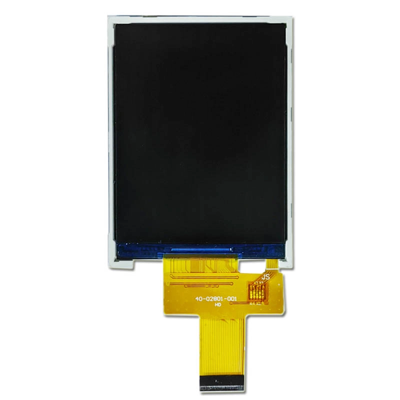
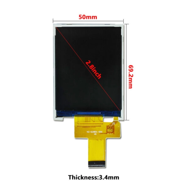
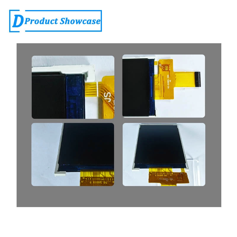
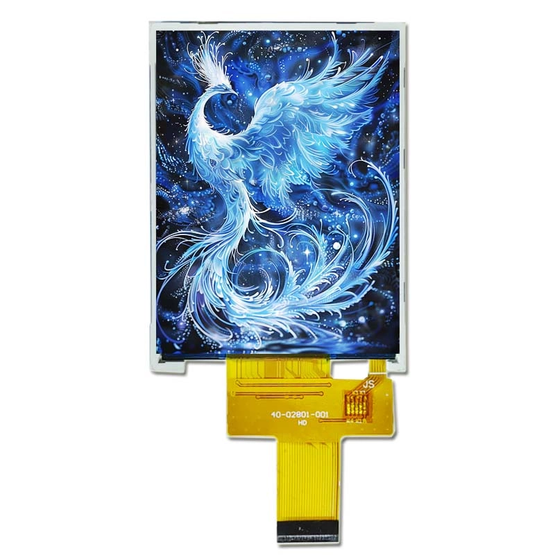
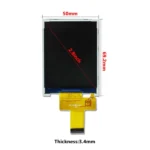
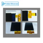
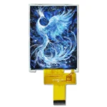
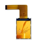
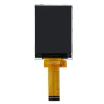
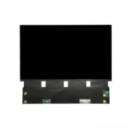
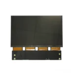
2.8-inch 240×320 MCU TFT LCD for industrial handheld devices, with 360-nit brightness, 3.3V supply, -20 to +70 C operation, 50 x 69.2 x 3.4 mm outline, and no touch panel in the standard configuration.
Product Attributes
| Brand | OEM / ODM |
|---|---|
| Size | 2.8 inch |
| Resolution | 240×320 |
| Interface | MCU |
| Brightness | Standard (200-450 nits) |
| Operating Temp | Industrial (-20 ℃ to +70 ℃) |
| Touchscreen | No Touch |
Description
2.8-Inch MCU TFT for Industrial Handheld Devices
This 2.8-inch TFT LCD module is configured for handheld equipment that needs a compact portrait screen, a 240×320 interface, and moderate indoor brightness. The confirmed module provides 360 nits brightness, uses a 3.3V supply, and has a 50 x 69.2 x 3.4 mm outline with a 43.2 x 57.6 mm active area. The standard product has no touch panel, allowing the device team to build the user interface around sealed keys, a navigation pad, trigger controls, or a rotary input.
Handheld integration is different from mounting a display in a stationary panel. Battery capacity, enclosure thickness, drop protection, cable movement, one-handed operation, and rapidly changing ambient light all influence the result. This page focuses on those handheld-device decisions so an engineering or procurement team can determine whether the module belongs in the prototype shortlist.
Confirmed Configuration for Sample Matching
| Display size | 2.8 inch |
|---|---|
| Resolution | 240×320 |
| Interface | MCU |
| Brightness | 360 nits |
| Touchscreen | No touch panel in standard configuration |
| Operating temperature | -20 to +70 C |
| Outline dimension | 50 x 69.2 x 3.4 mm |
| Active area | 43.2 x 57.6 mm |
| Power supply | 3.3V |
| LED lifetime | 20000 |
Use these confirmed values for initial comparison, but use the current controlled drawing and interface documentation for final mechanical and electrical release. The blank panel-model field on the earlier listing is not evidence of a specific controller IC or drop-in equivalent, so no such assumption should enter the design.
Handheld UI Planning: Readable in Motion and with One Hand
A handheld screen is often read while the operator is walking, wearing protective equipment, holding a probe, or moving between measurement points. The most important value should remain recognizable at a short glance. A 240×320 portrait layout can reserve the upper zone for device status and connection state, the center for the current measurement or task, and the lower zone for key labels and next actions.
Controls should correspond consistently to the labels shown near them. If the enclosure uses three or four keys, avoid menus that require touch-like gestures or hidden navigation. High-contrast focus states, explicit confirmation messages, and persistent battery or communication indicators reduce operator uncertainty. Error screens should explain the next action rather than display only a numeric code.
Font size must be validated at the real viewing distance. Handheld interfaces are sometimes designed on a desktop monitor and then reduced until labels become difficult to read on the physical module. Test the longest product-language translation, multiple measurement units, alarm states, low-battery messages, and sunlight transitions on an actual sample.
MCU Interface, Power Budget, and Firmware Behavior
The MCU interface can suit an embedded handheld architecture where the host already manages display initialization and graphical updates. Confirm the bus definition, data width, timing, pin assignment, voltage levels, reset behavior, and memory requirements from the applicable documentation. Screen size and resolution alone do not establish electrical compatibility with an existing board.
Battery-powered design requires more than checking the 3.3V line. Review the backlight driver, duty cycle, screen-on time, sleep behavior, wake sequence, and any inrush or brownout conditions. A field device may spend most of its time waiting for input, then need an immediate readable screen when the operator wakes it. Prototype testing should include repeated sleep and wake cycles at different battery states.
Firmware should handle interrupted power and communication errors without leaving a misleading frozen value on screen. Consider a visible stale-data indicator, reconnection state, and controlled blanking during reset. If only part of the interface changes frequently, regional updates may reduce traffic and processing load. The exact implementation depends on the host system and must be evaluated with the selected MCU.
Mechanical Design for a Device That Is Carried
The 50 x 69.2 x 3.4 mm outline must be evaluated together with the PCB, battery, fasteners, seals, and external housing. A handheld enclosure is repeatedly gripped, placed on benches, transported in cases, and sometimes dropped. The display should not become a structural load path. Retention features and cushioning should support the module without concentrating force on the viewing area.
Use the 43.2 x 57.6 mm active area to coordinate the visible window, but allow for mask and assembly tolerance. The cover window should protect the display from abrasion and cleaning, while its optical transmission and reflections are included in the brightness review. A recessed window may improve impact protection but can restrict off-axis viewing if the bezel is too deep.
FPC routing deserves special attention because the device will be handled and may experience repeated shock. Avoid a sharp fold at the module exit, conflict with screw bosses, or pressure from the battery. Confirm connector retention and service procedure. If the product is intended to be repaired, determine whether the display can be replaced without damaging bonded or sealed parts.
What 360 Nits Means in a Handheld Product
The confirmed 360-nit brightness offers additional margin over a basic indoor display, but it is not presented here as a direct-sunlight-readable specification. A handheld device may move from a warehouse to a vehicle, shaded outdoor work, or a bright inspection area within minutes. Reflections from the cover window can dominate the user’s perception even when the backlight remains unchanged.
Evaluate the module with the final cover material, surface treatment, air gap, border printing, and UI colors. A light background may improve some outdoor tasks but increase power demand and glare perception in others. A dark interface may be comfortable indoors but lose detail under strong reflections. The product team should test the actual operating modes rather than select a theme by appearance alone.
If reliable reading in open sunlight is mandatory, share the required conditions and thermal limits before quotation. A higher-brightness configuration, anti-glare treatment, bonding approach, or a different module may be appropriate, but each option affects cost, power, mechanics, and qualification.
No-Touch Operation for Field Reliability
The standard no-touch construction can be an advantage when operators wear gloves, the device is exposed to moisture, or inputs must be located by feel. Physical keys can provide deliberate activation and reduce accidental commands while the unit is carried. They can also simplify a sealed front panel when the screen sits behind a continuous protective window.
Button placement should still be reviewed with the on-screen layout. Frequently used actions should not require long menu paths, and destructive commands should require clear confirmation. If a future product version needs touch, define the touch technology, glove requirement, moisture behavior, cover thickness, border, bonding, and controller interface as a new integration package. Do not assume that a touch stack can be added without changing enclosure depth or optical performance.
Projects That May Fit This Module
Potential applications include portable test instruments, field calibration tools, maintenance terminals, barcode or asset-service devices with physical input, compact data collectors, battery diagnostic tools, handheld environmental monitors, and small medical or laboratory equipment subject to the customer’s own qualification. These examples describe integration patterns; they are not certifications or universal suitability claims.
The module may be a poor match for devices needing full outdoor readability, large touch targets, detailed imaging, high-frame-rate graphics, or a standard video input. It should also not be selected solely because another 2.8-inch panel has the same resolution. Outline, thickness, FPC, pinout, timing, optics, and viewing behavior all need comparison.
Environmental and Qualification Responsibilities
The specified -20 to +70 C operating range applies to the module. The finished handheld device can create different internal conditions due to battery charging, processor heat, sealing, sunlight exposure, or storage in a vehicle. Validate temperature at the display location, not only the room temperature. Condensation, cleaning chemicals, UV exposure, vibration, drop events, ESD, ingress protection, and regulatory requirements belong to the complete product qualification plan.
LCDind can review display-related drawings and requirements, but the equipment manufacturer must define and verify the finished device’s safety and environmental performance. Samples should be tested in the production-intent enclosure with the actual battery, board, firmware, protective window, and operating duty cycle.
Sample Approval and Supply Planning
During the sample phase, check cold and warm starts, wake-up time, image stability, backlight control, viewing through the cover, key-label alignment, cable clearance, and behavior at low battery. Run the device through representative field workflows rather than displaying only a static test image. Record the approved display settings and firmware version.
Before volume ordering, align the drawing revision, interface information, cosmetic inspection limits, packaging, traceability expectations, forecast, and change-notification process. If the product family may need customized FPC routing, brightness, cover glass, branding, or touch, define those variants early so samples and purchasing records cannot be mixed.
RFQ Checklist for an Industrial Handheld Project
- Device function, operator workflow, and intended screen examples
- Host MCU, proposed interface, voltage, firmware platform, and available memory
- Enclosure, window, PCB, battery, and FPC-routing drawings
- Indoor, shaded outdoor, or direct-sunlight conditions and required viewing distance
- Drop, vibration, sealing, glove, cleaning, and temperature expectations
- Key layout or planned touch-input requirements
- Prototype quantity, annual volume, program lifetime, and qualification schedule
- Existing display model and exact reason for replacement, if applicable
Engineering FAQ
Is this module a drop-in replacement for another 2.8-inch 240×320 display?
Not automatically. Compare the outline, thickness, active area, FPC position, connector, pin assignment, timing, voltage, viewing result, and firmware initialization before treating any module as interchangeable.
Can 360 nits be used outdoors?
It may be readable in some shaded or transitional conditions, but this listing does not claim direct-sunlight readability. Test the production window and UI under the specified ambient light, or request a review of brighter alternatives.
Why choose physical keys instead of touch?
Keys can support gloves, tactile operation, deliberate input, and a sealed protective window. The correct choice depends on the operator workflow and enclosure; the standard module itself has no touch panel.
What information is needed to check battery operation?
Provide the power architecture, backlight control plan, expected screen-on duty cycle, sleep and wake behavior, battery range, internal temperature, and host interface. System power cannot be concluded from the 3.3V entry alone.
Can LCDind customize the module?
Potential changes such as FPC routing, connector direction, backlight, cover glass, touch integration, and packaging can be reviewed against quantity and project requirements. They must be confirmed as a specific configuration before sampling.
Send the enclosure drawing, host-board information, operating conditions, sample quantity, and annual forecast through the engineering inquiry form. LCDind will review whether this 2.8-inch handheld-display configuration fits the project or whether another optical or mechanical solution is more appropriate.
Additional information
| Brand | OEM / ODM |
|---|---|
| Size | 2.8 inch |
| Resolution | 240×320 |
| Interface | MCU |
| Brightness | Standard (200-450 nits) |
| Operating Temp | Industrial (-20 ℃ to +70 ℃) |
| Touchscreen | No Touch |
About brand
Source OEM / ODM LCD panels for OEM, replacement and industrial integration projects. Submit size, resolution, interface, brightness, lifecycle and annual quantity for review.
Engineering FAQ
Q: Can this 2.8 inch TFT LCD module be supplied with a touch screen?
A: The standard listing is No touch panel in standard configuration. LCDind can review resistive touch, capacitive touch, cover lens, bonding, and controller matching when the finished device needs operator input.
Q: What customization options are available for this display?
A: Common custom work includes brightness tuning, FPC length, connector direction, cover glass, logo placement, touch integration, bonding, packaging, and production inspection requirements.
Q: How should the MCU interface be confirmed?
A: Confirm timing, pinout, voltage, cable direction, firmware support, and EMC layout with the host board before sample approval. LCDind can review drawings and interface notes before production.
Q: Can the brightness be adjusted for a different environment?
A: The confirmed brightness is 360 nits. If the display is used behind cover glass or in stronger ambient light, share the target environment so LCDind can review backlight and thermal options.
Q: What information should buyers send for an RFQ?
A: Send quantity, forecast, interface, mechanical drawing, brightness target, touch requirement, operating temperature, logo needs, and any current panel model or datasheet.
Q: Is this display suitable for outdoor equipment?
A: This module is mainly for compact equipment and controlled-light use. For outdoor or direct-sunlight projects, LCDind should review brightness, cover glass, bonding, thermal design, and sealing requirements first.
Shipping and Delivery
Q: What is the MOQ?
A: The MOQ for our products is 1 piece. We are able to provide support throughout the testing process.
Q: What about the delivery time?
A: We have products in stock and can ship them within 3 working days.
Q: Does your product have any warranty?
A: Yes, we offer a warranty that ensures the LCD will function properly upon receipt. However, please note that we do not provide guarantees for any damage caused during use.
Q: What’s your payment method?
A: We accept several payment methods, including T/T (bank transfer), and PayPal.
Q: What’s your shipping method?
A: Thank you for your inquiry. We offer various shipping methods to suit different needs.
For small quantity orders, we use UPS Air-Express, DHL, FedEx, TNT, or EMS Express service. These options are safe and fast.
For large quantity orders, we typically work with the buyer’s cargo agent in China. Alternatively, we can arrange for air or sea transportation.
Please let us know your preferred shipping method and we will do our best to accommodate your request.
Q: Do you offer custom solution?
A: Yes, we offer custom solutions if our standard products do not meet the buyer’s requirements. Please let us know your specific needs, and we will work with you to create a tailored solution that meets your business needs.
Q: How to Contact us?
A: Send your Inquiry Details in the Below, Click “Send” Now!