13
2.8 Inch TFT LCD Module for Compact Instrument Panels
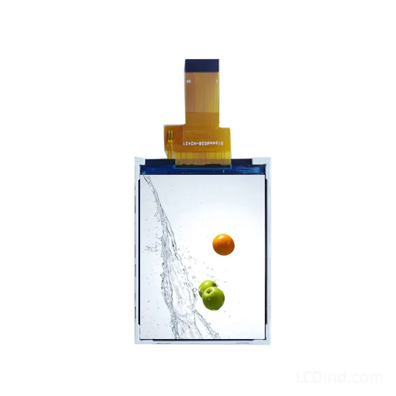
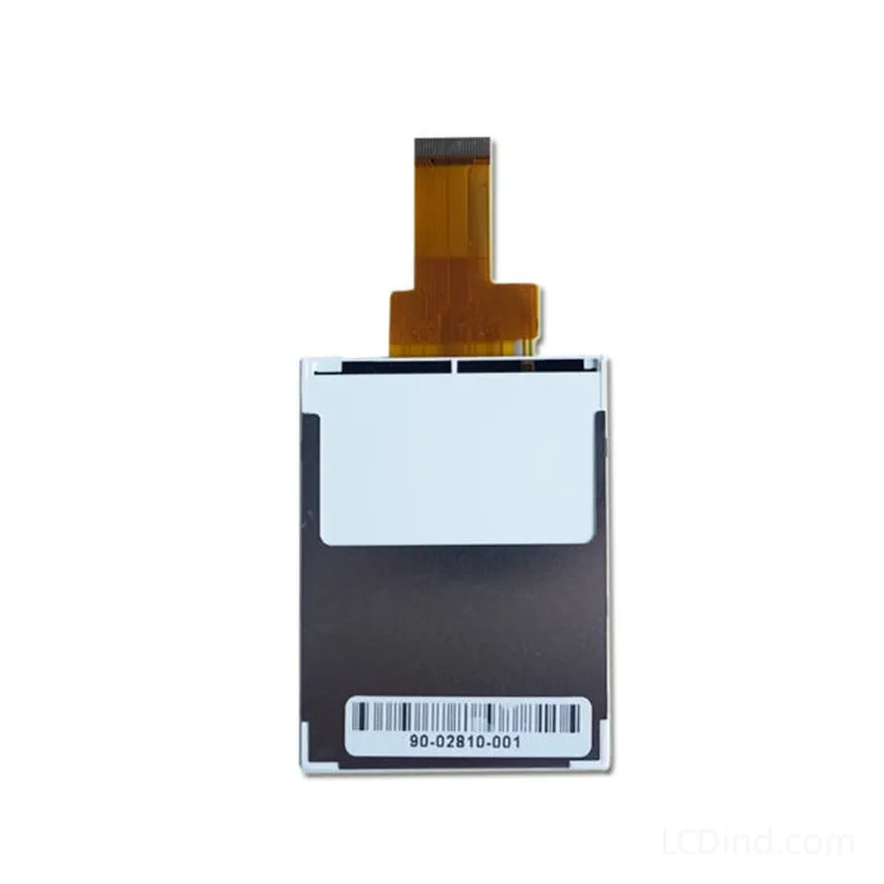
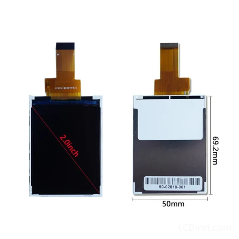
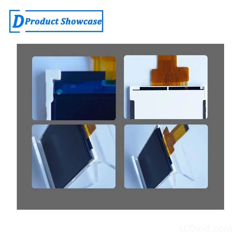
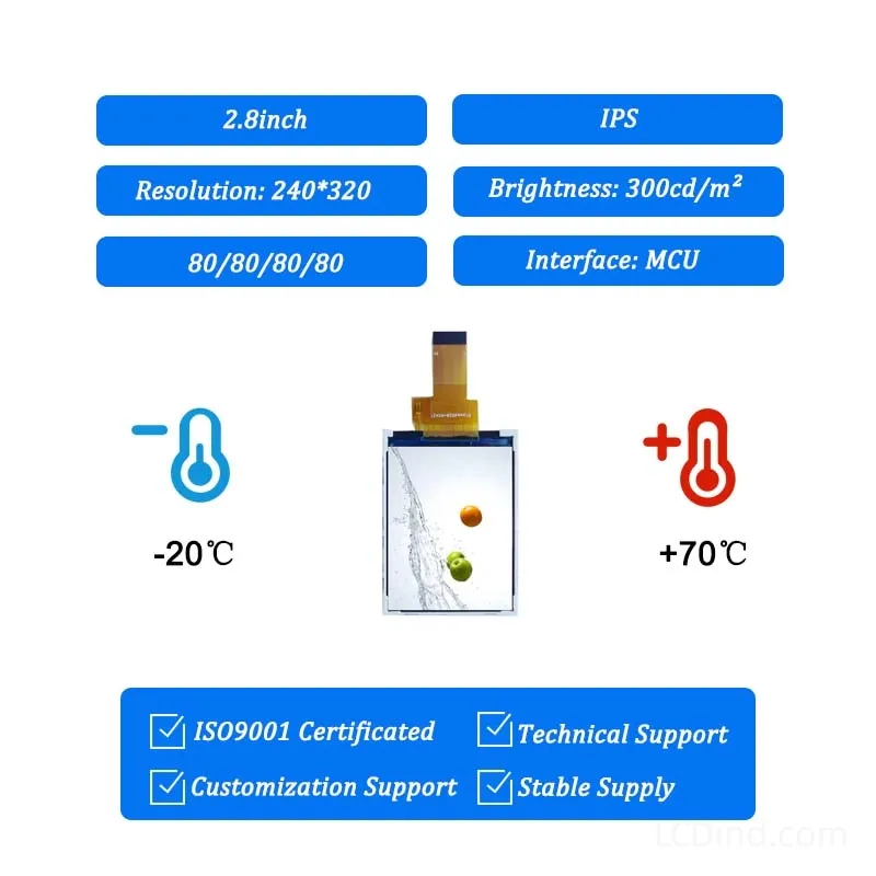
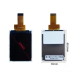
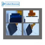
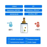
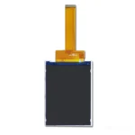
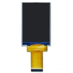
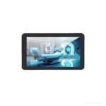
2.8-inch 240×320 MCU TFT LCD for compact instrument panels, with 300-nit brightness, 3.3V supply, -20 to +70 C operation, 50 x 69.2 x 2.3 mm outline, and no touch panel in the standard configuration.
Product Attributes
| Brand | OEM / ODM |
|---|---|
| Size | 2.8 inch |
| Resolution | 240×320 |
| Interface | MCU |
| Brightness | Standard (200-450 nits) |
| Operating Temp | Industrial (-20 ℃ to +70 ℃) |
| Touchscreen | No Touch |
Description
2.8-Inch 240×320 MCU TFT for Compact Instrument Panels
This 2.8-inch TFT LCD module is intended for compact instruments that need a portrait display for measured values, operating states, warning messages, simple trends, and setup parameters. Its 240×320 pixel format gives an engineering team more vertical room than a very small status screen while keeping the module within a 50 x 69.2 x 2.3 mm outline. The standard configuration uses an MCU interface, operates from a 3.3V supply, provides 300 nits brightness, and does not include a touch panel.
The module is most relevant when the product already has physical keys, a rotary encoder, membrane switches, or another established input method. It can support a clear information hierarchy without forcing the enclosure and firmware teams to accommodate a touch stack. Typical projects to evaluate include portable measuring instruments, bench equipment, compact process indicators, service tools, handheld diagnostic units, and controller front panels used mainly under controlled indoor lighting.
Confirmed Module Parameters
| Display size | 2.8 inch |
|---|---|
| Resolution | 240×320 |
| Interface | MCU |
| Brightness | 300 nits |
| Touchscreen | No touch panel in the standard configuration |
| Operating temperature | -20 to +70 C |
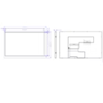
| Module outline | 50 x 69.2 x 2.3 mm |
| Active area | 43.2 x 57.6 mm |
| Power supply | 3.3V |
| LED lifetime | 20000 |
These values should be treated as the selection baseline. Final approval should still be based on the current drawing, interface definition, sample, and the conditions of the complete instrument.
Designing a Legible Instrument Interface at 240×320
A compact screen does not need a crowded interface. For an instrument panel, the primary reading should receive the largest type and strongest contrast. Units, limits, channel labels, and operating mode can occupy a secondary visual level. Alarm information should not depend on color alone; an icon, text label, border, or inversion makes the warning easier to recognize in changing light and for different operators.
The portrait format works well for a top-to-bottom workflow: equipment state at the top, the current value in the center, and soft-key labels or secondary measurements near the bottom. It can also present a short menu without reducing the main reading to an impractical size. Before firmware is finalized, the UI team should test the longest translated label, worst-case numeric value, negative sign, decimal positions, and all alarm combinations on the actual 240×320 canvas.
Refresh strategy matters when the host MCU has limited graphics memory or bus bandwidth. A measuring instrument often does not require every region to refresh at video rate. Static labels, slowly changing values, and small trend areas can be updated separately. This reduces unnecessary data transfers and can make the interface feel more stable. The exact MCU timing, bus width, initialization sequence, and pixel transfer method must be confirmed from the applicable technical documentation rather than assumed from display size alone.
Mechanical Integration Before Enclosure Tooling
The 43.2 x 57.6 mm active area defines the visible image, but the enclosure must be designed around the full 50 x 69.2 x 2.3 mm module outline. A window based only on the active area can interfere with the frame, FPC, connector, or assembly tolerance. The mechanical review should include the bezel opening, printed mask, gasket width, retaining features, PCB position, cable route, FPC bend radius, and service access.
For a protective window, check the visible-area margin from normal viewing angles. A mask that is too tight can hide the first or last pixels after tolerance stack-up. A mask that is too open may expose the non-active border. If the instrument uses a gasket for dust resistance or vibration control, it should load the supported perimeter rather than press unpredictably on the active display area.
The 2.3 mm module thickness is only one part of the installed stack. The housing window, adhesive, air gap, protective lens, mounting structure, connector height, and PCB components behind the display can determine the real package depth. LCDind should receive the relevant enclosure section and board drawing before the customer commits to production tooling.
Optical Use and the 300-Nit Boundary
The confirmed 300-nit brightness is appropriate to evaluate for indoor instruments and equipment used in controlled ambient light. It should not be interpreted as a sunlight-readable claim. A smoked lens, anti-glare surface, printed overlay, air gap, or narrow viewing angle through a deep bezel can reduce perceived brightness and contrast. The display should therefore be reviewed behind the production-intent window, not only as an uncovered sample on a workbench.
For equipment that moves between indoor and bright outdoor locations, tell LCDind the expected illuminance, viewing distance, duty cycle, and enclosure thermal limits. A brighter backlight may improve readability but can affect power, heat, optical balance, and long-term integration. Those trade-offs should be evaluated as a separate configuration rather than silently transferred to this standard 300-nit specification.
Night operation also deserves consideration. If the instrument is used in a dark room, vehicle cabin, laboratory, or maintenance area, firmware-controlled dimming may be more important than peak brightness. The control range and backlight drive method should be checked during prototype evaluation.
Why the Standard No-Touch Configuration Can Be Useful
Physical controls remain practical in many industrial instruments. Operators may wear gloves, work in wet or dusty conditions, or need to change a value without looking directly at the screen. Buttons and encoders can also give a consistent control path when the display is mounted behind a thick protective cover. In these cases, omitting a touch panel avoids extra stack height, optical loss, touch-controller integration, and calibration work.
If the finished product does require touch input, it should be treated as a defined engineering change. The team needs to specify resistive or capacitive operation, cover-lens material and thickness, visible area, border printing, bonding method, controller interface, glove or water behavior, and expected environment. A touch option is not interchangeable with the confirmed no-touch module without checking mechanics and electronics.
Application Fit and Selection Boundaries
This display can be considered for compact data loggers, pressure or flow indicators, portable analyzers, test fixtures, laboratory controllers, charger or power-system interfaces, service terminals, and embedded instruments with a portrait front panel. The common requirement is a modest amount of structured information rather than video, detailed mapping, or a large multi-window HMI.
It is less suitable when the project requires direct-sunlight readability, a wide graphical dashboard, high-resolution imaging, a standard touch interface, or a plug-and-play HDMI connection. In those cases, the engineering team should evaluate a different brightness class, resolution, interface, or module size instead of forcing the product architecture around this unit.
The stated -20 to +70 C operating range describes the module specification, not the environmental rating of the finished instrument. The enclosure designer remains responsible for internal temperature rise, condensation control, sealing, mechanical shock, vibration, ESD, EMC, and any regulatory requirements. Testing should be performed in the assembled device under representative operating conditions.
Prototype and Production Approval
A useful sample review covers more than whether the display powers on. Confirm the initialization sequence, stable image transfer, color and orientation, backlight control, power-up and power-down behavior, reset recovery, and the longest expected operating session. Inspect the screen through the final window from the real working distance and angles. Mechanical fit should be checked with the production-intent connector and cable route.
For repeat production, procurement should freeze the approved drawing, interface version, incoming inspection criteria, cosmetic limits, packing method, and change-notification expectations. If the project may require an alternate FPC length, connector direction, brighter backlight, cover lens, or touch integration, raise that requirement before sample approval so the correct configuration is evaluated.
Information to Send for an Engineering Review
- Instrument function and a sketch or screenshot of the intended 240×320 UI
- Host MCU, proposed bus definition, voltage, timing information, and connector preference
- Enclosure window, module pocket, PCB position, and cable-routing drawings
- Ambient lighting, viewing distance, backlight duty cycle, and internal temperature estimate
- Input method, including keys, encoder, or any proposed touch requirement
- Prototype quantity, annual forecast, qualification schedule, and target production date
- Existing panel model or drawing if this is a replacement or second-source project
Engineering FAQ
Is 300 nits enough for an industrial instrument?
It can be suitable for controlled indoor lighting, but readability depends on the protective window, reflections, viewing angle, interface colors, and working distance. Outdoor or direct-sunlight use requires a separate optical and thermal review.
Can the interface be connected directly to any microcontroller?
No universal compatibility should be assumed. Confirm the MCU bus type, pin assignment, voltage, timing, initialization data, memory capacity, and update requirements against the current documentation and host design.
Why is the active area smaller than the module outline?
The active area is the image-producing region. The outline also includes the display structure and connection area. Enclosure and PCB clearance must use the full outline and drawing, while the visible window is coordinated with the active area and mask tolerance.
Can a touch panel be added later?
A touch version may be reviewed, but it changes stack height, optics, mechanics, electronics, and qualification. Specify the touch technology and cover-lens requirements before the sample stage.
What should be approved before volume ordering?
Approve the current drawing, interface documentation, sample performance, window appearance, cable route, environmental result, inspection criteria, packing, and exact ordered configuration. Send these records with the forecast when requesting a production quotation.
Request an engineering review with the host-board information, enclosure drawing, operating conditions, quantity, and project schedule. LCDind will confirm whether this standard 2.8-inch MCU TFT is suitable or whether a different optical, mechanical, or touch configuration should be evaluated.
RFQ Checklist
- Confirm the host MCU interface mode, bus width, initialization sequence, connector direction, and expected screen refresh behavior.
- Provide the instrument enclosure drawing, visible-window size, FPC bend route, keypad or encoder layout, and required front-panel clearance.
- State whether the standard no-touch configuration is required, or whether a resistive touch, PCAP touch, cover lens, or bonding stack should be quoted separately.
- Confirm the target operating environment, especially indoor lighting level, service temperature range, vibration exposure, and whether 300 nits is sufficient after the final front window is installed.
- Share prototype quantity, annual forecast, preferred packing, inspection standard, and any label or traceability requirements for repeat production.
Engineering Review Note
For compact instruments, the display approval should be connected to the full user-interface and enclosure review, not only the electrical power-on test. LCDind recommends checking the longest numeric value, alarm state, menu depth, front-window tolerance, and cable route before confirming this 2.8 inch MCU module for batch procurement.
Additional information
| Brand | OEM / ODM |
|---|---|
| Size | 2.8 inch |
| Resolution | 240×320 |
| Interface | MCU |
| Brightness | Standard (200-450 nits) |
| Operating Temp | Industrial (-20 ℃ to +70 ℃) |
| Touchscreen | No Touch |
About brand
Source OEM / ODM LCD panels for OEM, replacement and industrial integration projects. Submit size, resolution, interface, brightness, lifecycle and annual quantity for review.
Engineering FAQ
Q: Can this 2.8 inch TFT LCD module be supplied with a touch screen?
A: The standard listing is No touch panel in standard configuration. LCDind can review resistive touch, capacitive touch, cover lens, bonding, and controller matching when the finished device needs operator input.
Q: What customization options are available for this display?
A: Common custom work includes brightness tuning, FPC length, connector direction, cover glass, logo placement, touch integration, bonding, packaging, and production inspection requirements.
Q: How should the MCU interface be confirmed?
A: Confirm timing, pinout, voltage, cable direction, firmware support, and EMC layout with the host board before sample approval. LCDind can review drawings and interface notes before production.
Q: Can the brightness be adjusted for a different environment?
A: The confirmed brightness is 300 nits. If the display is used behind cover glass or in stronger ambient light, share the target environment so LCDind can review backlight and thermal options.
Q: What information should buyers send for an RFQ?
A: Send quantity, forecast, interface, mechanical drawing, brightness target, touch requirement, operating temperature, logo needs, and any current panel model or datasheet.
Q: Is this display suitable for outdoor equipment?
A: This module is mainly for compact equipment and controlled-light use. For outdoor or direct-sunlight projects, LCDind should review brightness, cover glass, bonding, thermal design, and sealing requirements first.
Shipping and Delivery
Q: What is the MOQ?
A: The MOQ for our products is 1 piece. We are able to provide support throughout the testing process.
Q: What about the delivery time?
A: We have products in stock and can ship them within 3 working days.
Q: Does your product have any warranty?
A: Yes, we offer a warranty that ensures the LCD will function properly upon receipt. However, please note that we do not provide guarantees for any damage caused during use.
Q: What’s your payment method?
A: We accept several payment methods, including T/T (bank transfer), and PayPal.
Q: What’s your shipping method?
A: Thank you for your inquiry. We offer various shipping methods to suit different needs.
For small quantity orders, we use UPS Air-Express, DHL, FedEx, TNT, or EMS Express service. These options are safe and fast.
For large quantity orders, we typically work with the buyer’s cargo agent in China. Alternatively, we can arrange for air or sea transportation.
Please let us know your preferred shipping method and we will do our best to accommodate your request.
Q: Do you offer custom solution?
A: Yes, we offer custom solutions if our standard products do not meet the buyer’s requirements. Please let us know your specific needs, and we will work with you to create a tailored solution that meets your business needs.
Q: How to Contact us?
A: Send your Inquiry Details in the Below, Click “Send” Now!