13
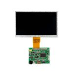
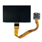
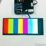
Universal LCD Controller Board solutions. Convert HDMI/VGA signals to LVDS, EDP, or MIPI. Custom firmware support for industrial display panels.
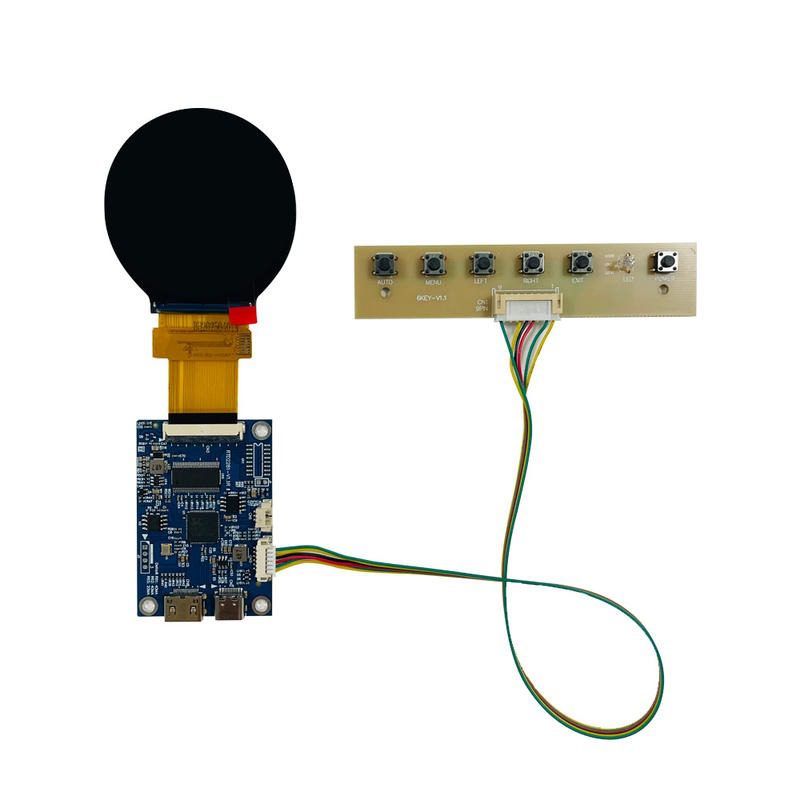
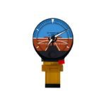
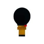
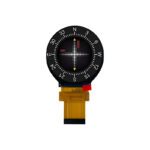
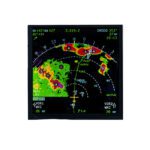
2.1 inch round IPS TFT LCD module for simulator instruments, with 480×480 resolution, 300 cd/m2 brightness, 53.28 x 53.28 mm active area and -20 to 70C operation.
This 2.1 inch 480×480 round IPS TFT LCD module is intended for compact flight simulator instruments and circular equipment interfaces. The current public page confirms 480×480 resolution, 300 cd/m² brightness, 53.28 x 53.28 mm active area, round IPS TFT construction, and -20 to 70℃ operating temperature. It also mentions customization support for LCD size, FPC layout, viewing angle, backlight design, CTP size, and customer logo. Other items, including interface, connector pinout, full outline dimension, power supply, and backlight lifetime, are not clearly listed in the public page and should be confirmed from drawing or datasheet before purchase.
| Size | 2.1 inch |
|---|---|
| Resolution | 480×480 |
| Brightness | 300 cd/m2 |
| Active Area | 53.28 x 53.28 mm |
| Operating Temperature | -20 to 70℃ |
| Display Type | Round IPS TFT LCD module |
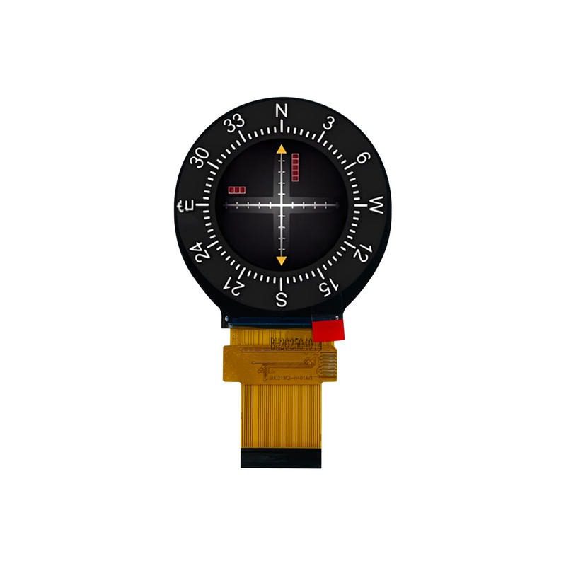
Round LCD modules are useful in flight simulator projects because many cockpit references are circular or gauge-like. This 2.1 inch module can be considered for compact attitude indicators, engine status dials, standby instruments, training consoles, home cockpit panels, and other circular UI elements where a square or rectangular display would create unnecessary mechanical trimming. The 480×480 resolution gives enough pixel density for needles, arcs, numbers, colored zones, and warning marks when the UI is designed specifically for a small round visible area.
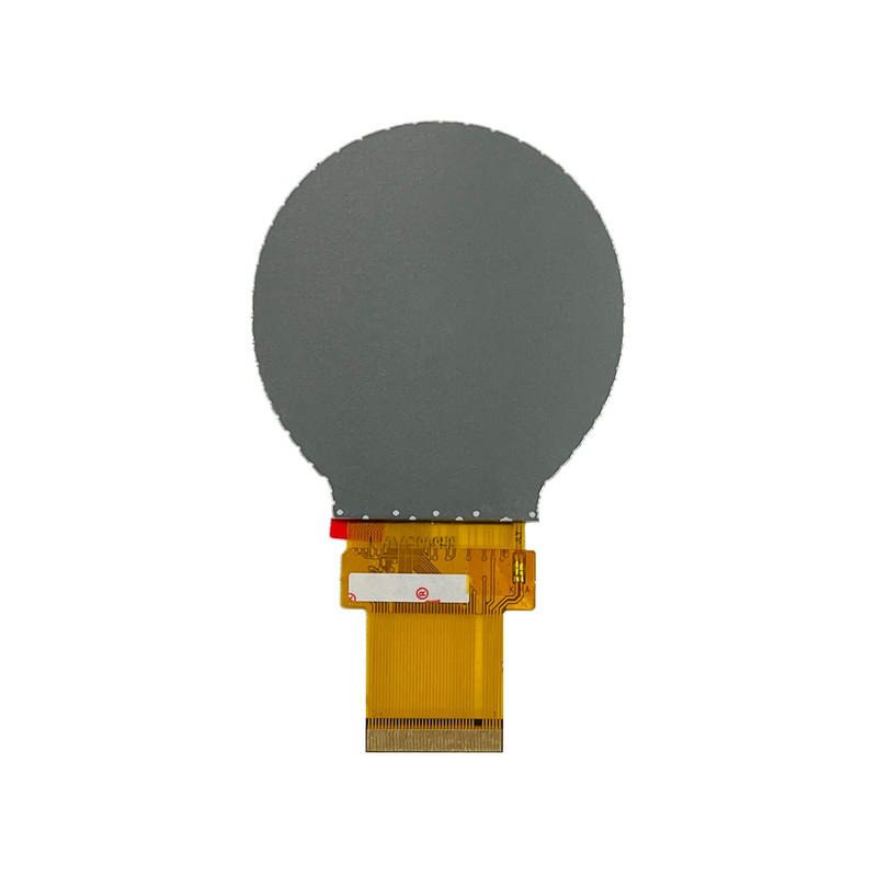
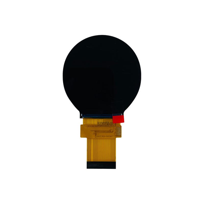
The confirmed active area is 53.28 x 53.28 mm, but the page does not give a complete module outline. That means the buyer should not design only from the active diameter. Ask for the full mechanical drawing, FPC exit, connector location, cover-lens recommendation, and mounting clearance before cutting the panel or bezel. Round displays also need careful alignment because a slight rotation error can make a gauge face look visibly wrong even when the display is electrically functional.
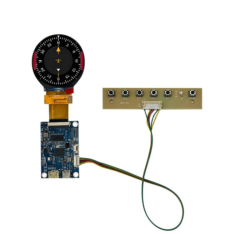
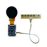
The public page does not clearly confirm the signal interface. Flight simulator builders often use HDMI controller boards, Raspberry Pi platforms, microcontrollers, or custom embedded boards, and each option changes the driver requirement. Before quoting, provide the host platform, available connector, expected refresh behavior, UI update rate, and whether an off-the-shelf controller board is required. LCDind should confirm timing, initialization, pinout, and driver support before the module is approved.
The listed 300 cd/m² brightness can work for indoor simulator cockpits where ambient light is controlled. It should not be treated as an outdoor sunlight-readable display. If the simulator is used in a bright training room, under acrylic overlays, or behind tinted glass, evaluate contrast, anti-glare treatment, dimming range, and night-mode behavior. For cockpit-like use, low-brightness control is also important so the display does not overpower neighboring panels during dark-room training.
The page explicitly mentions FPC layout, viewing angle, backlight design, CTP size, and logo options. These are useful for OEM simulator equipment, but they require drawings and volume expectations. A custom FPC or cover lens can improve assembly, yet it also affects tooling cost and lead time. Procurement should separate prototype needs from production requirements so LCDind can recommend whether standard sampling or custom development is the practical route.
For simulator instruments, the display module is only one part of the user experience. The graphics should be drawn for a round active area from the beginning, with the important scale marks and numbers kept away from the visible edge. If the front bezel hides part of the square pixel matrix, confirm the exact visible diameter. Test needle motion, color bands, warning flags, and night-mode colors on the real module rather than judging from a desktop preview.
A practical sample approval should include boot behavior, refresh rate, viewing angle, brightness adjustment, gauge alignment, cable movement, and long-duration operation inside the simulator panel. If the display is used with a controller board, approve the controller and cable together with the LCD. If a custom FPC or CTP is requested, freeze the mechanical drawing before pilot build so the same configuration can be repeated in production.
The specifications above are taken from the current public product page and should be used as selection inputs, not as a final integration approval. Before sample purchase or batch order, LCDind should review the drawing, host interface, optical stack, operating environment, quantity plan, and any customization request. This reduces the risk of selecting a display that matches the headline but fails the enclosure, firmware, brightness, or supply requirements of the finished equipment.
Not without confirming the controller or host interface. The page confirms display characteristics but not a complete PC connection method.
It is generally a controlled-light indoor brightness level. Final readability depends on cover lens, room lighting, UI contrast, and dimming settings.
Ask for the datasheet, outline drawing, connector pinout, interface timing, and power requirements before designing the enclosure.
Q: What is the MOQ?
A: The MOQ for our products is 1 piece. We are able to provide support throughout the testing process.
Q: What about the delivery time?
A: We have products in stock and can ship them within 3 working days.
Q: Does your product have any warranty?
A: Yes, we offer a warranty that ensures the LCD will function properly upon receipt. However, please note that we do not provide guarantees for any damage caused during use.
Q: What’s your payment method?
A: We accept several payment methods, including T/T (bank transfer), and PayPal.
Q: What’s your shipping method?
A: Thank you for your inquiry. We offer various shipping methods to suit different needs.
For small quantity orders, we use UPS Air-Express, DHL, FedEx, TNT, or EMS Express service. These options are safe and fast.
For large quantity orders, we typically work with the buyer’s cargo agent in China. Alternatively, we can arrange for air or sea transportation.
Please let us know your preferred shipping method and we will do our best to accommodate your request.
Q: Do you offer custom solution?
A: Yes, we offer custom solutions if our standard products do not meet the buyer’s requirements. Please let us know your specific needs, and we will work with you to create a tailored solution that meets your business needs.
Q: How to Contact us?
A: Send your Inquiry Details in the Below, Click “Send” Now!
🔒 Your data is secure. We usually reply within 24 hours.